I have finished my digital model. It's been sent off to get properly printed with an Objet printer. I'm listening to the Sunshine soundtrack. And I just want the computer to show me how to create a beautiful image of my model.
I started out with a program I'm reasonably familiar with. 3dsMax is something I've used to create renders ever since I started using it in DSDN 104 last year. It's been a trusty friend, but I much admit I don't know it as well as I'd like to. I'm able to get something out of it at least, something that doesn't look like utter crud.
After trying out the previous render, I wanted to attempt something a bit different, so I did, I changed the location of lights, and also added a roof, so as to give the chrome something to reflect vertically.
Once I got to a certain point, I realised that 3dsMax wasn't giving me the results I wanted, as it's a very advanced program, with uses far beyond rendering. I decided to switch to a program that is exclusively for rendering, as this would give me a much more definite result that would look good and not take hours to set up. The above image is out of the new program and already looking significantly better.
Experimenting with different sets, I can get a host of different results, but most of them look great! It's really great what a switch in programs can allow you to do. This one used a soap bubble texture on the plane the model is hovering above. The colour distortions on the horizon at the back left really add to the scene.
One of the final renders I've done at this point, I decided to enhance the model somewhat by adding extra elements that change the way the model is seen. I switched the ground plane's material, and then changed the material on some parts of the model itself. The interior space in the centre I changed to black, and the little six sections on either side of the central orb I made into little lights, which can be seen most effectively in the reflection on the ground plane.
Gotta keep rendering!
Saturday, April 20, 2013
INDN 252: Icarus? Show Me Something Beautiful.
Labels:
INDN 252,
Process,
Second Year
Thursday, April 18, 2013
INDN 252: Let's See How Far We've Come
Now that I've designed the model and done a preliminary print on the Up! printers, I decided to move into a more expensive and more detailed print, with just the basics of the joint as the printed elements, so as to keep costs down for myself.
As you can see, the joint element printed beautifully and retained all of the detail that I built into the Solidworks model, which I don't think I'll ever quite get over. Just the fact that there's no input from me between where I put the file into the printing folder to me getting it back, and yet it's exactly what I wanted. This resin is more of a pale, clear, yellow colour (which isn't quite captured in the photo), but it's still quite nice.
I definitely want to get my final model printed in the white, more opaque resin, but this is certainly a good starting point for my moving joint. The motion is perfect. Exactly what I designed, and exactly what I got. The outer support material was a a bit of a bitch to clean off, especially in the little gaps between the moving parts, but that's okay. I got there in the end.
One thing however that needs definite changing is the size on my knee-cap element. It gets stuck between the overarching curve elements, and needs to be shrunk down a little bit. But other than that, looking good!
Labels:
INDN 252,
Process,
Second Year
Tuesday, April 16, 2013
INDN 252: Starting On Something Real
Now that I've achieved my final model in Solidworks, it's time to actually get some 3-D printing done. I'm pleased with how the form looks in Solidworks, but getting it to look good in the real world can usually mean something else entirely.
Fortunately for us students, we have access to some mini Up! printers, which we're allowed to use for free. These printers print in ABS plastic, with support material generated from the same material that the model is made of. This allows to effectively do a lot of rapid prototyping at minimal cost. It's a fantastic tool that we have access to, and a lot of people put it to amazing use.
So I did some test prints of my model, trying to establish how well the model turns out for use. I wanted to make sure that the size was okay and that the model would allow for use in the way that I intended.
Cleaning the support material off these was a bit of a mission, but I got there in the end. This part actually worked out quite nicely, as I had it oriented on its side, so the material printed really well on one side, but the other side has a lot of damage from the support material being taken off.
The second part suffered a bit more from the problem of it being a bit too thin to print well. But oh well. That's okay, It's just a little test print after all. The form is still there, and definitely still works as a whole.
Putting these together intact is impossible, as the way that I've designed this model is for it to be printed as an assembly. So, to put the two pieces together, I had to break part of the second piece to fit onto the other part. The Up! printers aren't capable of doing assemblies very well and with the precision I need them to, but that's okay.
Now, to look at some rendering!
Fortunately for us students, we have access to some mini Up! printers, which we're allowed to use for free. These printers print in ABS plastic, with support material generated from the same material that the model is made of. This allows to effectively do a lot of rapid prototyping at minimal cost. It's a fantastic tool that we have access to, and a lot of people put it to amazing use.
So I did some test prints of my model, trying to establish how well the model turns out for use. I wanted to make sure that the size was okay and that the model would allow for use in the way that I intended.
Cleaning the support material off these was a bit of a mission, but I got there in the end. This part actually worked out quite nicely, as I had it oriented on its side, so the material printed really well on one side, but the other side has a lot of damage from the support material being taken off.
The second part suffered a bit more from the problem of it being a bit too thin to print well. But oh well. That's okay, It's just a little test print after all. The form is still there, and definitely still works as a whole.
Putting these together intact is impossible, as the way that I've designed this model is for it to be printed as an assembly. So, to put the two pieces together, I had to break part of the second piece to fit onto the other part. The Up! printers aren't capable of doing assemblies very well and with the precision I need them to, but that's okay.
The range of motion in this test model is equal to that of the digital model, which I designed to be that of the actual knee, which is pretty fantastic. It works well, and I'm glad that that the look and feel of the model isn't lost from the digital to the printed model.
Now, to look at some rendering!
Labels:
INDN 252,
Process,
Second Year
Sunday, April 14, 2013
INDN 252: So-lid-works! So-lid-works! So-lid-works!
So, I've made the move into Solidworks now. Using my dimension sketch as my primary reference, and the architectural concept as my second point of reference, I embarked on what I consider to be the most daunting and most exciting part of the whole process. I've come to love Solidworks over the course of second year so far. It's pretty cool, and an extremely powerful program, and I find I'm really starting to think in a way that I can then translate into Solidworks models.
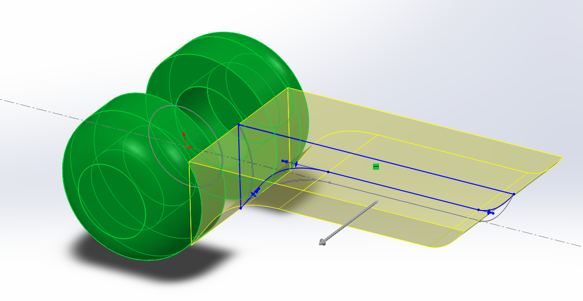
The part of the model that I started on first was the lesser of the two large segments. This piece involves the part of the model that "latches on" to the other half, surrounding the extruded axle with circular segments that will allow it to move.
This half is the part that draws a lot from the architectural precedent, in the way that the extrusion grows out of the central point. One of the elements that I also wanted to incorporate into this joint was the idea that it wasn't built, but rather grown, along a very simple geometric formula. The curves build the idea of an organic element, but ultimately they are still controlled and dictated by the linear elements of the model.
One of the parts that I wanted to build in were the pieces that the Bubble ship incorporated. I really liked the hexagonally symmetrical air vents. Now obviously my model doesn't need air vents, but as a subtle little aesthetic, they can work quite nicely.
I wanted to split the main section in two, so as to allow the model to have an architecturally senseless but graceful air. The architecture precedent really played on this idea of "Does that even really fit people in it??", but it looked incredible and just oozed pure futurism. The subtle curvature used in combination with the featuresque curvature really played on the idea of challenging the angularity as well as submitting to it.
One of the final elements that I built into this part was the slot going all the way through, an element that I had involved right from the beginning of the sketch. The double rounded triangles are a form that I've seen somewhere before, but I can't quite place where. The give the user a point of reference on the main form for the rotation as well as being aesthetic.
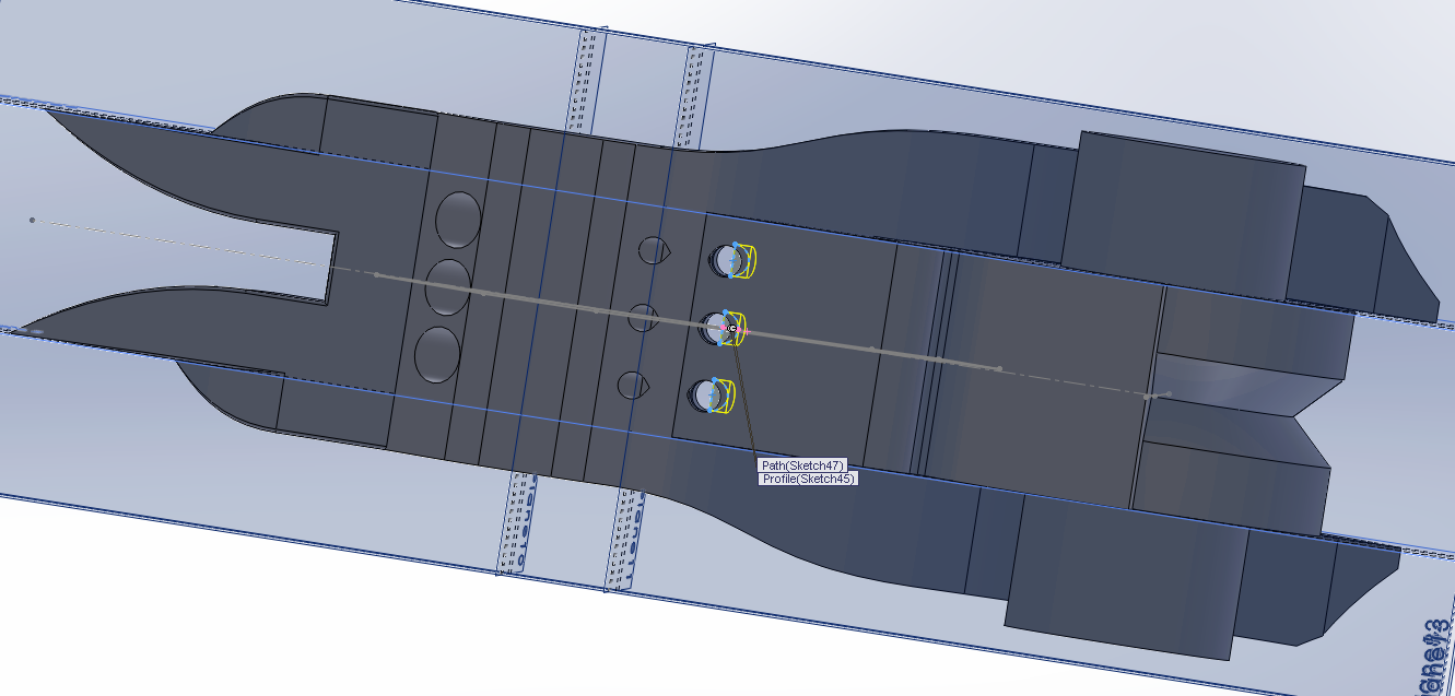
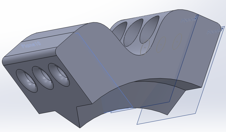
Another piece that I had to build into the model was a set of holes that pierce through the model, allowing for the elastic thread I've bought to be put through the model. This hole then transforms to a bigger hole on the far side of the model, so that I can attach a crimp to the thread, and then let the crimp fall back into the hole, so that there's no extraneous pieces of thread hanging around.
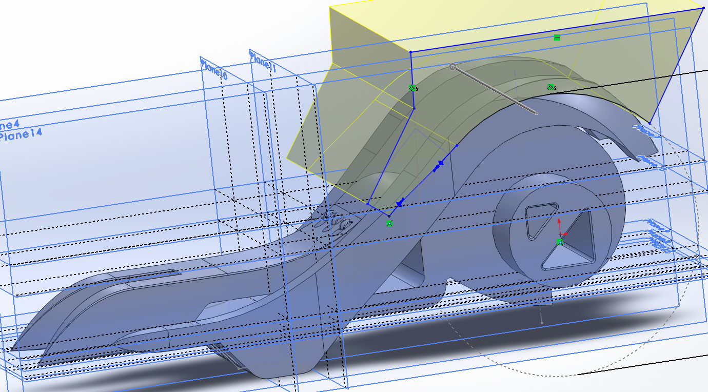
Part 2 is the much more extensive and tricky part to do, since it contains far more elements and therefore I need to give it more consideration. I started with the overarching curve and the spiral inner curve, which would allow the knee cap part to slide into the joint a little bit. This little consideration is really important in capturing the motion as a collective motion of multiple parts.
Once I had the overarching curve that would act as the stop for the bottom half of the joint, the rest of the top half could come together. I this step I really tried to capture the basic form I was going for. Lots of extrusions and perfect measurements needed to be made. For this piece to get the aesthetic I wanted, I wanted it to feel like it was a whole range of separate pieces coming together, but working as one.
This half of the model I also split into two at the end, so as to establish a connection between that half and the other half. This also creates a suggestion for where to hold the model, as the spaces create an edge that is comfortable to hold. For the knee joint to sit comfortably in place and actually stay in its place, it really needs to have a sort of rail, which I incorporated into the spiral edge.
One of the coolest elements that I built into this part of the model is the diagonal slope on the front curvature. It's quite a striking addition (or subtraction, technically!) and I really feel like it makes the model have a much more organic feel to it, with a combination of the harder lines and the stranger angled edges.
I then worked a little more on creating some additions to the overall shape, as well as making the model lose a bit of fat overall. One of the things that my tutor told me to experiment with was to remove some matter, making some more interesting surfaces visible.Again, most of the ideas for this element came from the feature wall in the Mass Effect architecture.
Once I had a concrete, workable form for the top half of the joint, I needed to come up with a solution for how to allow my elastic threads to fit into the model. I could have done the same thing that I did to the bottom half and have a top section that allowed the thread to fit into there. But I thought that since I just added a section in the space beneath the two bottom angular sections, I should use that area, as it would mean I'd have to put the thread through the model in a very interesting way.
Once I had that section working well, I decided to slim down the top overarching stopper curves, as they were a little fat now that I'm trying to refine the form into something a bit more elegant. The loss of matter and general filleting of some of the edges I wanted to smooth has allowed me to embody the images I've explored in this form.
This form is probably the more interesting one out the two main pieces so far, but that's okay. It's the half that's got a bigger role to play, so it deserves more attention. I managed to really slim it down by highlighting some interesting edges and the like, so it's good that I've been able to bring those out more.
The edges that I've exposed and made definitely put this form into a futuristic feel, and I think they make the model shine.
The next element I have to design is the knee cap. It has to be a subtle element, while at the same time still be a part that you notice, and actually see as being a working piece. The piece is going to have to be much more functional than aesthetic, since it's rather small.
Since I'm working at just getting the pieces to fit together perfectly, the way this piece fits to the other pieces is just with a simple triangular rail, that I've replicated on both sides. For this piece, I again utilised the Sebastien Voerman patent-pending Shifting Hole technology, so that the crimp can fall back into the hole and not be an issue.
Once I get to see it all together, it actually looks pretty sweet! Once I put all the parts together as an assembly, I did a motion study, and the pieces very much emulate the actual range of motion that the knee has. Which is very exciting.
Time to do some little prints!
The part of the model that I started on first was the lesser of the two large segments. This piece involves the part of the model that "latches on" to the other half, surrounding the extruded axle with circular segments that will allow it to move.
This half is the part that draws a lot from the architectural precedent, in the way that the extrusion grows out of the central point. One of the elements that I also wanted to incorporate into this joint was the idea that it wasn't built, but rather grown, along a very simple geometric formula. The curves build the idea of an organic element, but ultimately they are still controlled and dictated by the linear elements of the model.
One of the parts that I wanted to build in were the pieces that the Bubble ship incorporated. I really liked the hexagonally symmetrical air vents. Now obviously my model doesn't need air vents, but as a subtle little aesthetic, they can work quite nicely.
I wanted to split the main section in two, so as to allow the model to have an architecturally senseless but graceful air. The architecture precedent really played on this idea of "Does that even really fit people in it??", but it looked incredible and just oozed pure futurism. The subtle curvature used in combination with the featuresque curvature really played on the idea of challenging the angularity as well as submitting to it.
One of the final elements that I built into this part was the slot going all the way through, an element that I had involved right from the beginning of the sketch. The double rounded triangles are a form that I've seen somewhere before, but I can't quite place where. The give the user a point of reference on the main form for the rotation as well as being aesthetic.
Another piece that I had to build into the model was a set of holes that pierce through the model, allowing for the elastic thread I've bought to be put through the model. This hole then transforms to a bigger hole on the far side of the model, so that I can attach a crimp to the thread, and then let the crimp fall back into the hole, so that there's no extraneous pieces of thread hanging around.
Part 2 is the much more extensive and tricky part to do, since it contains far more elements and therefore I need to give it more consideration. I started with the overarching curve and the spiral inner curve, which would allow the knee cap part to slide into the joint a little bit. This little consideration is really important in capturing the motion as a collective motion of multiple parts.
Once I had the overarching curve that would act as the stop for the bottom half of the joint, the rest of the top half could come together. I this step I really tried to capture the basic form I was going for. Lots of extrusions and perfect measurements needed to be made. For this piece to get the aesthetic I wanted, I wanted it to feel like it was a whole range of separate pieces coming together, but working as one.
This half of the model I also split into two at the end, so as to establish a connection between that half and the other half. This also creates a suggestion for where to hold the model, as the spaces create an edge that is comfortable to hold. For the knee joint to sit comfortably in place and actually stay in its place, it really needs to have a sort of rail, which I incorporated into the spiral edge.
One of the coolest elements that I built into this part of the model is the diagonal slope on the front curvature. It's quite a striking addition (or subtraction, technically!) and I really feel like it makes the model have a much more organic feel to it, with a combination of the harder lines and the stranger angled edges.
I then worked a little more on creating some additions to the overall shape, as well as making the model lose a bit of fat overall. One of the things that my tutor told me to experiment with was to remove some matter, making some more interesting surfaces visible.Again, most of the ideas for this element came from the feature wall in the Mass Effect architecture.
Once I had a concrete, workable form for the top half of the joint, I needed to come up with a solution for how to allow my elastic threads to fit into the model. I could have done the same thing that I did to the bottom half and have a top section that allowed the thread to fit into there. But I thought that since I just added a section in the space beneath the two bottom angular sections, I should use that area, as it would mean I'd have to put the thread through the model in a very interesting way.
Once I had that section working well, I decided to slim down the top overarching stopper curves, as they were a little fat now that I'm trying to refine the form into something a bit more elegant. The loss of matter and general filleting of some of the edges I wanted to smooth has allowed me to embody the images I've explored in this form.
This form is probably the more interesting one out the two main pieces so far, but that's okay. It's the half that's got a bigger role to play, so it deserves more attention. I managed to really slim it down by highlighting some interesting edges and the like, so it's good that I've been able to bring those out more.
The edges that I've exposed and made definitely put this form into a futuristic feel, and I think they make the model shine.
The next element I have to design is the knee cap. It has to be a subtle element, while at the same time still be a part that you notice, and actually see as being a working piece. The piece is going to have to be much more functional than aesthetic, since it's rather small.
Once I get to see it all together, it actually looks pretty sweet! Once I put all the parts together as an assembly, I did a motion study, and the pieces very much emulate the actual range of motion that the knee has. Which is very exciting.
Time to do some little prints!
Labels:
INDN 252,
Process,
Second Year
Subscribe to:
Posts (Atom)