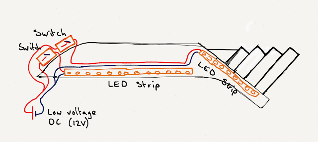
The next trickiest bit I needed to figure out was the circuitry of the light. I wanted to have the two sections of the light to be individually controlled, so this meant that I had to create a parallel circuit, with a switch on each loop of the circuit. This would keep the voltage the same over the two sections as well, which is very important, as the LEDs run on 12V, and I need to use a 12V DC adapter.
One thing that I discovered about LED strips is that, unlike typical electrical components, both the positive and the negative points are at the same end of the strip. The strips can be cut up into 3-LED segments if so desired, which meant that I was able to get 1m of LEDs and then cut it into one longer section, and one shorter section.
Unfortunately, the LED stripping I got only had electrical "tails" (pre-soldered-on wires) at one end, so I was going to have to solder on two wires to the second section. This was an issue because the two points were about 2mm apart, and I have shaky hands. So you can imagine my troubles.
I bought all my electrical gear from Advance Electrical (an electrical wholesaler in the area) and was also able to get an LED driver (essentially a 12V DC power adapter, basically like a laptop charger) from them as well. This proved to actually be the most expensive part of my project, but the good part is that I can re-use it.
Because of this little $3 piece of equipment, I'm able to re-use the LED driver and I don't have to splice into the actual cable running off the LED driver. It's just a little female socket that fits neatly onto the male connector from the LED driver. that I can remove at will.
For my switches, I deliberated for ages. I ended up deciding on some unobtrusive black ones. I wish I had been able to get them in white, but oh well. They don't look too bad really. Originally intended for 230VAC connections, I discovered I can use them for my low voltage circuit just fine. And they are a nice size too, fitting into the holes I made for them nicely.


No comments:
Post a Comment